In the world of CNC (Computer Numerical Control) metal cutting, preparation is everything. A well-prepared Drawing Exchange Format (DXF) file can mean the difference between a flawless cut and costly mistakes. Whether you're using a laser, plasma or waterjet cutter, making sure your DXF file is optimized for the process is critical to achieving precision, efficiency and quality. In this article, we provide a comprehensive DXF file preparation checklist to help designers, fabricators, and hobbyists streamline their metal cutting projects.
The Importance of DXF File Preparation
Properly preparing a DXF file minimizes errors, saves material and reduces cutting time. Poorly optimized files can cause machine malfunctions, wasted material, and substandard results.
Benefits of proper preparation:
- Accuracy: Ensures that the final product matches the design.
- Efficiency: Reduces machine downtime and processing time.
- Cost savings: Eliminates material waste and repeated cuts.
- Machine longevity: Minimizes unnecessary wear and tear on equipment.
Common problems without preparation:
- Overlapping lines that cause double cuts.
- Open paths that interrupt the cutting process.
- Incorrect scaling resulting in mismatched dimensions.
Pre-Design Considerations
Before you begin creating DXF files, consider the following:
1. Understand the cutting method
- Laser Cutting: Requires precision and clean paths; best for intricate designs.
- Plasma Cutting: Suitable for thicker metals, but less detailed.
- Waterjet Cutting: Ideal for a variety of materials and thicker cuts.
2. Choose the right material
- Consider the thickness, durability, and type of metal.
- Match the design to the material properties to avoid overdesign.
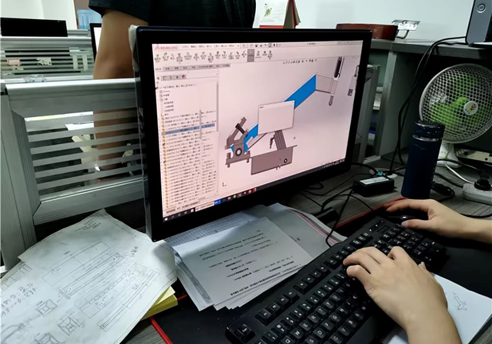
3. Use the right CAD software
- Choose software that can export compatible DXF files, such as AutoCAD, CorelDRAW, or Fusion 360.
- Familiarize yourself with the software's tools for node reduction, layer management, and path verification.
Step-by-Step Checklist for Preparing a DXF File
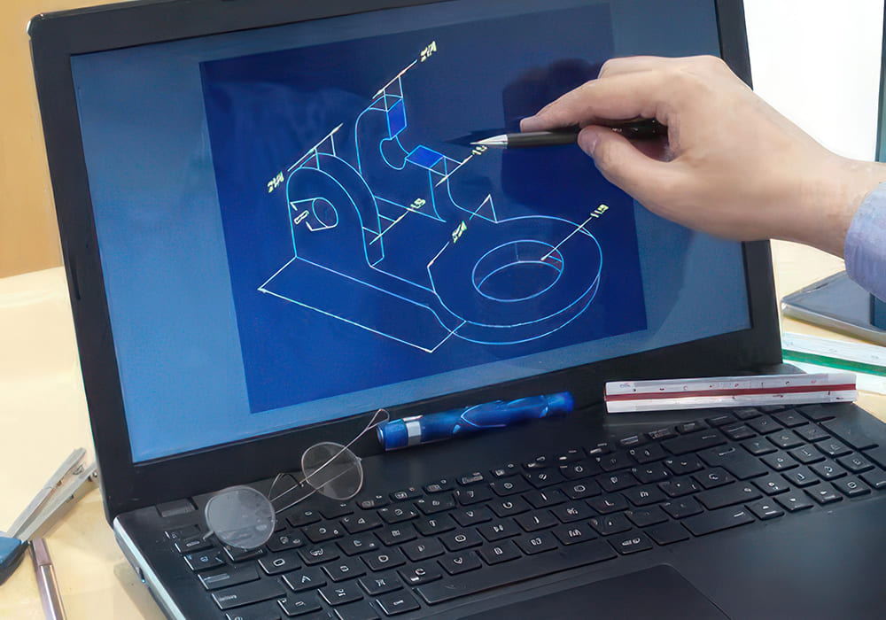
Follow these steps to ensure your file is ready for cutting:
Step 1: Clean the design
- Remove unnecessary elements: Delete construction lines, annotations, or fiducials that are not needed for cutting.
- Eliminate overlapping lines : Checks for and removes duplicate or intersecting paths that could confuse the cutter.
- Merge connected lines: Use the "join" tool in your CAD software to create smooth, continuous paths.
Step 2: Ensure Path Continuity
- Check Closed Paths: Ensure that all shapes are closed loops, as open paths can disrupt the cutting process.
- Check for Gaps: Use zoom and diagnostic tools to identify and close small gaps in the design.
Step 3: Optimize Line Weight
- Set the line weight to zero or a minimum value (such as 0.01mm). This ensures that the cutting machine focuses only on the paths and not on the line thickness.
Step 4: Manage Layers
- Separate layers for cutting, engraving, and marking. For example:
- Layer 1: Cutting paths.
- Layer 2: Engraving details.
- Layer 3: Reference marks.
- Clearly mark each layer to avoid confusion during machine setup.
Step 5: Scale and Measure
- Verify that the scale of the design matches the intended size.
- Verify that the dimensions allow for material thickness and kerf width (the material removed during cutting).
Step 6: Simplify the Design
- Reduce Nodes: Simplify curves and shapes by reducing the number of nodes without compromising design integrity.
- Avoid Over-Detailing: Remove excessive detail that may slow the cutting process or be too fine for the material.
Step 7: Test Compatibility
- Use computer-aided manufacturing (CAM) software to simulate the cutting process.
- Run a virtual test to identify potential problems such as incomplete cuts or misaligned paths.
Troubleshooting Common DXF Problems

Even with careful preparation, some problems may arise. Here's how to troubleshoot:
1. Overlapping or duplicate lines
- Problem: Leads to redundant cuts, wasting time and material.
- Solution: Use the "Purge" or "Overkill" command in the CAD software to remove duplicates.
2. Open Paths
- Problem: Causes the machine to pause or stop in the middle of a cut.
- Solution: Use path inspection tools to locate and close gaps.
3. Scaling errors
- Problem: Final product dimensions don't match the design.
- Solution: Check the units (millimeters vs. inches) and adjust the scaling settings during export.
4. Excessive Nodes
- Problem: Results in jagged cuts or machine slowdowns.
- Solution: Use the Simplify tool to reduce nodes while maintaining smooth curves.
5. Compatibility issues
- Problem: DXF file doesn't load or process correctly.
- Solution: Save the file in a compatible DXF version (e.g. R12 for older machines).
Best practices for error-free cutting

1. Standardize file names
- Use descriptive file names that include the project name, material type, and cutting method. For example: "ProjectName_Steel_LaserCut_R12.dxf"
2. Saving Multiple Versions
- Save a master file for edits and export machine-ready versions separately.
3. Collaborate with fabricators
- Share your DXF file with the cutting team and ask for feedback.
- Incorporate their suggestions to improve compatibility and efficiency.
4. Create a template for repeated projects
- Use a template with predefined layers, line weights, and scaling settings to streamline future projects.
5. Keep your software up to date
- Use the latest version of your CAD software to ensure access to new features and improved compatibility.
Advanced Tips for Seamless DXF File Preparation

For more experienced users, these advanced tips can further refine your DXF files:
1. Use node reduction strategically
- Simplify curves in areas that don't affect design aesthetics while maintaining detail in critical areas.
2. Use color coding
- Assign colors to layers to differentiate between operations, making it easier for the machine operator to understand the design.
3. Automate file cleanup
- Use plug-ins or scripts in CAD software to automate repetitive tasks such as closing paths and removing duplicates.
4. Optimize for material usage
- Arrange designs to minimize material waste by using nesting software to position parts efficiently.
5. Integrate QR Codes or Labels
- Embed QR codes or text labels in non-cut areas for easy identification during assembly.
Conclusion
Preparing a DXF file for machining is both an art and a science. By following this comprehensive checklist, designers and fabricators can ensure that their files are optimized for seamless cutting, resulting in precise, high-quality results. Proper preparation not only increases efficiency and accuracy, but also reduces costs and minimizes errors.
By paying attention to detail and following best practices, you can transform your designs into flawless metal creations. Whether you're working on a one-of-a-kind piece or a high-volume production run, well-prepared DXF files are the foundation of successful metal fabrication. Take the time to refine your files and your cutting projects will run smoothly every time.