The accuracy of CNC cutting is highly dependent on correctly configured cutting parameters. When working with metals such as steel, aluminum and copper, the choice of parameters such as feed rate, power and kerf width can have a significant impact on the quality, efficiency and cost of production. DXF files play a crucial role in this process by serving as the blueprint for CNC machines, but their effectiveness depends on how well they are tailored to specific cutting requirements.
This article provides a detailed guide to configuring DXF files for optimal performance when working with different types of metals, focusing on essential cutting parameters and practical tips.
Understanding Cutting Parameters
Cutting parameters are the settings that determine how a CNC machine interacts with the material. The most important parameters include
Parameter | Description Effect | Impact |
Feed Rate | The speed at which the cutting tool moves through the material. | Affects cutting time and edge quality. |
Power Settings | Laser, plasma, or waterjet power. | Determines depth of cut and heat affected zones. |
Kerf Width | Width of material removed during cutting. | Influences accuracy and material consumption. |
Focus Height | Distance between cutting tool and material surface. | Affects accuracy and edge smoothness. |
These parameters vary depending on the metal to be cut, its thickness, and the cutting technology used.
Configuring DXF Files for Steel
Steel is one of the most commonly used metals in manufacturing, known for its strength and versatility. However, cutting steel requires special settings to achieve clean, precise edges.
- Laser Cutting Parameters
- Power: High power (1-3 kW) for thicker sheets; lower power for thin steel.
- Feed Rate: Moderate speed to avoid thermal distortion.
- Kerf Width: Typically 0.1-0.3 mm, depending on laser focus.
Steel Thickness | Power (kW) | Feed Rate (mm/s) | Kerf Width (mm) |
1mm | 1.0 | 15 | 0.1 |
5 millimeters | 2.5 | 8 | 0.2 |
10mm | 3.0 | 4 | 0.3 |
- Adjust the DXF file
- Add tolerances to account for thermal expansion (typically 0.1-0.2mm).
- Use simplified cutting paths for thick sections to reduce processing time.
- Plasma Cutting Parameters Plasma cutting is ideal for thicker steel. Use high amperage settings and slower feed rates to ensure smooth cuts.
Configuring DXF Files for Aluminum
Aluminum is lightweight, corrosion-resistant, and widely used in industries such as aerospace and construction. However, its softness and thermal conductivity present unique challenges.
- Key considerations
- Avoid Burrs: Use a high feed rate to minimize heat buildup that can cause burrs along the edges.
- Heat Management: Lower power settings to prevent distortion.
- Laser Cutting Parameters
- Power: Moderate (1-2 kW).
- Feed Rate: Higher than steel to reduce heat input.
- Kerf Width: Typically 0.1-0.2 mm.
Aluminum thickness | Power (kW) | Feed Rate (mm/s) | Kerf Width (mm) |
1mm | 1.0 | 20 | 0.1 |
5mm | 1.8 | 12 | 0.15 |
10mm | 2.0 | 6 | 0.2 |
- Customizing the DXF File
- Ensure that curves and edges are smoothed to prevent tool drag.
- Include kerf width allowances to maintain dimensional accuracy.
- Waterjet Cutting Parameters Waterjet cutting is often preferred for aluminum due to its cold cutting process, which completely eliminates heat distortion. Kerf allowances are typically not required.
Configuring DXF Files for Copper
Copper's reflectivity and high thermal conductivity make it difficult to cut, especially with laser-based systems.

- Key challenges
- Reflectivity: Can damage laser systems if not properly managed.
- Heat Dissipation: Requires more power to maintain cutting depth.
- Laser Cutting Parameters
- Power : Very high (3 kW or more).
- Feed Rate: Slower to ensure penetration.
- Groove Width: 0.15-0.3 mm.
Copper thickness | Power (kW) | Feed Rate (mm/s) | Kerf Width (mm) |
1mm | 3.0 | 10 | 0.15 |
5mm | 4.0 | 5 | 0.25 |
10mm | 6.0 | 2 | 0.3 |
- Customize the DXF file
- Add larger tolerances due to slower cutting speeds and heat effects.
- Consider using thicker lines to reduce the risk of incomplete cuts.
- Alternative Methods Plasma or waterjet cutting is often more effective for copper as these methods are not affected by reflectivity.
Test and iterate cutting parameters

Prototyping is an essential step when working with new metals or designs. Follow these steps to ensure optimal results:
- Digital Simulations: Use CAD software to simulate the cutting process.
- Test runs: Cut small sections of scrap material to verify settings.
- Adjustments: Revise the DXF file based on test results, fine-tuning tolerances and pathing.
Safety Considerations
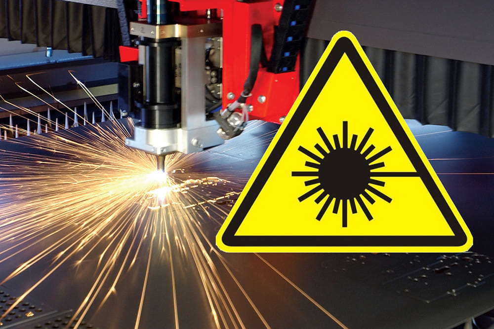
Different metals and cutting methods present unique safety challenges. For example:
- Steel: Requires proper ventilation to control fumes from laser or plasma cutting.
- Aluminum: Sparks from plasma cutting can ignite fine aluminum dust.
- Copper: Reflective surfaces can be a hazard to laser operators.
Always follow machine safety protocols and wear appropriate personal protective equipment (PPE).
Conclusion
Selecting the right cutting parameters for different metals is both a science and an art. By understanding the properties of materials such as steel, aluminum and copper and customizing DXF files to account for these characteristics, fabricators can achieve high-quality cuts with minimal waste. Prototyping, iteration, and collaboration with CNC operators are key to refining these processes. With these principles in mind, you can optimize DXF files for any metalworking project.